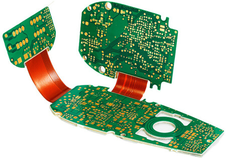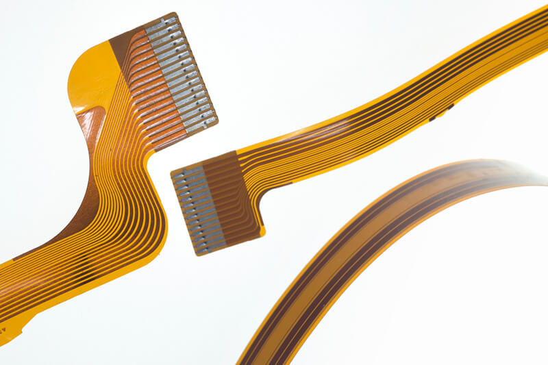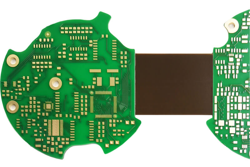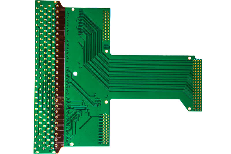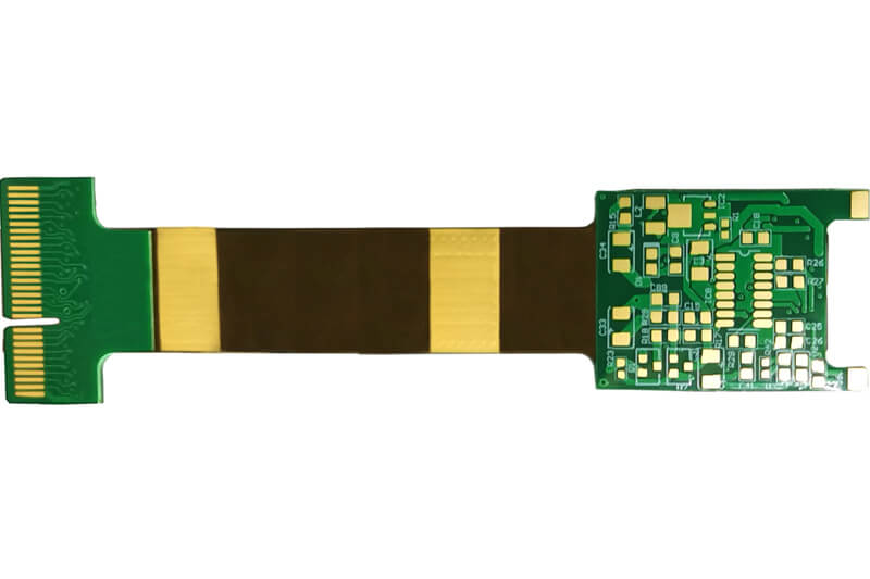
Flex and Rigid-Flex PCBs will include some degree of flexibility. This can be in the whole circuit (Flex) or a dynamic flexible join between two or more rigid boards (Rigid-Flex). The main advantage is often considered as having the ability to physically fit into products where no other solution would work but they have many other advantages.
Advantages include:
DK-Daleba is a leading supplier of Flex and Rigid Flex circuit, and we can manufacture your boards in a wide range of materials and surface finishes depending on your exact application. Full capabilities are detailed below, and a pdf can be downloaded here.
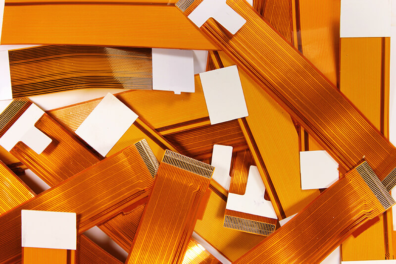
Contact us today and our sales engineers will discuss your exact requirement Download Flex / Flex-Rigid BrochureFlex circuits are also referred to as a FPC (Flexible Printed Circuit), Flex Circuit Boards, Flex PCBs, Flex Circuits, or Flexible Printed Circuits. They consist of a thin insulating polymer film encapsulating the conductor circuit. Polyimides are popular for construction as they offer high temperature opportunities for assembly or product environment. Flex circuits can be manufactured as a connector or designed for use with components. Rigid stiffeners can be included. They can be constructed as single sided, double sided or multi-layered.

Item | Sample (Order Area <3m2) | Batch (Order Area ≥3m2) |
---|---|---|
Main Materials | ||
Insulation Layer | CVL, Ink | CVL, Ink |
Colour of coverlay | Yellow, Black, White | Yellow, Black, White |
Colour of ink | Yellow, Green | Yellow, Green |
Dielectric layer | 0.012mm-0.1mm | 0.025-0.1mm |
Additional Materials | ||
FR-4 Stiffener | 0.1-3.2mm | 0.1-3.2mm |
PI Stiffener | 0.075-0.225mm | 0.075-0.225mm |
Steel reinforcement | 0.2-0.6mm | 0.2-0.4mm |
Other Materials | 3M tape, snap dome, electromagnetic shielding, lid-off film, micro-sticking film | 3M tape, snap dome, electromagnetic shielding, lid-off film, micro-sticking film |
Structure | 1+n+1 ; 1+1+n+1+1 ; 2+n+2 (needs review) | 1+n+1 ; 1+1+n+1+1 ; 2+n+2 (needs review) |
F+R (needs review), cu+F+cu (needs review), R+F+R+F+R (needs review), R+F+R | R+F+R | |
Layers | ≤14L | ≤8L |
Board Thickness | 0.06-0.35mm | 0.1-0.35mm |
Tolerance of Board Thickness | Flexible Area 0.03mm;PI Stiffener Area 0.05mm;FR-4 Stiffener Area 0.1mm | Flexible Area 0.03mm;PI Stiffener Area 0.05mm;FR-4 Stiffener Area 0.1mm |
Min single unit Size | PCB Size: 5mm*15mm-310mm*510mm | PCB Size:5mm*15mm-310mm*510mm |
Copper Thickness | Outer layer 2oz, Inner layer 2oz | Outer layer 1oz, Inner layer 1oz |
Outline | Breakaway Tab, Single PCB | Breakaway Tab, Single PCB |
Surface Treatment | HASL, HASL lead free (single-side FPC only), ENIG, OSP (no-stiffener only) | ENIG |
Rigid Flex are hybrid boards and by definition consist of a Flex board with a Rigid circuit component incorporated in the design. These hybrid circuits can be a Flex with an FR4 stiffener, or two or more rigids connected with Flex circuits. Rigid Flex circuits offer the best of both flexible circuits and rigid boards combined in one PCB.
Rigid Flex circuits are extremely versatile and can be used in a wide range of applications. Designers often consider they are ultimate solution for making use of the available packaging space. Increased product reliability and overall reduced assembly costs are also drivers for this technology.
Item | Sample (Order Area <3m2) | Batch (Order Area ≥3m2) | |
---|---|---|---|
Material | |||
Tg170 | S1000-2M, IT180A | S1000-2M, IT180A | |
Hi-Tg FR4 (halogen-free) | S1165 | S1165 | |
Hi-speed material: | needs review | needs review | |
Structure | 1+n+1 ; 1+1+n+1+1 ; 2+n+2 (needs review) | ||
F+R (needs review), cu+F+cu (needs review), R+F+R+F+R (needs review), R+F+R | R+F+R | ||
Layer | ≤18L | ≤16L | |
Board Thickness | 0.5-3.2mm | 0.5-3.2mm | |
Copper Thickness | Outer layer 2oz, Inner layer 2oz | Outer layer 2oz , Inner layer 2oz | |
Outline | |||
Processes | Rigid Area | Single PCB; V-Cut; Breakaway Tab; Breakaway Tab+Stamp Holes; Breakaway Tab+V-Cut; Breakaway Tab+V-Cut+Stamp Holes | Single PCB;V-Cut; Breakaway Tab; Breakaway Tab+Stamp Holes; Breakaway Tab+V-Cut; Breakaway Tab+V-Cut+Stamp Holes |
Flexible Area | Breakaway Tab, Single PCB | Breakaway Tab, Single PCB | |
Tolerance of Size | Rigid Area | 0.1mm | 0.15mm |
Flexible Area | 0.05mm | 0.1mm | |
Drilling | |||
Drill bit(min) for mechanical drill | 0.15(Board Thk≤1.2mm)-6.2mm | 0.2-6.2mm | |
The gap between hole wall for different webs (CAF): | IPC standard | 12mil | 12mil |
Military standard | 16mil | 16mil | |
Hole to trace distance (after compensation) for one lamination | 4L-5.5mil; 6L-6.5mil; 8L-7mil; 10L-8mil; 12-18L-10mil | 4L-6mil; 6L-7mil; 8L-8mil; 10L-10mil; 12-18L-12mil | |
Surface treatment | HASL, HASL lead free, ENIG, Immersion Tin (needs review), Immersion Silver (needs review), OSP, HASL+Gold Finger (needs review), ENIG+Gold Finger, ENEPIG OSP+Gold, Finger (needs review), ENIG+OSP (needs review) | HASL, HASL lead free, ENIG, Immersion Tin (needs review), Immersion Silver (needs review), OSP, HASL+Gold Finger(needs review), ENIG+Gold Finger, ENEPIG, OSP+Gold, Finger (needs review), ENIG+OSP (needs review) | |
Solder Mask | Colour | Green, Yellow, Black, Blue, Red, White, Matt Green, Matt Black | Green, Yellow, Black, Blue, Red, White, Matt Green, Matt Black |
Silkscreen | Colour | White, Yellow, Black | White, Yellow, Black |
Sign up to receive a monthly PCB newsletter containing the latest information in the world of PCBS including new technology and supply chain information.
Sign up Now